- Get link
- X
- Other Apps
- Get link
- X
- Other Apps

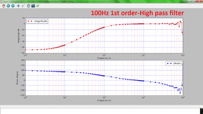
Creating A Bode Analyzer From A Microcontroller Hackaday

Solved Problem 7 10 Points What Capacitor Value Would B

Low Pass Filter Bode Plot Butterworth Fi 1443396 Png


Active High Pass Filter Op Amp High Pass Filter

How Filters Work Animations

Multisim Tutorial Instrumentation Lab

Rl High Pass Filter One Zero One Pole Magnitude Phase And 3db Frequency

Bode Diagram Of The Complementary Filters The Lowpass

Active High Pass Filter Circuit Design And Applications

8 4 Advanced Rc Filters High Pass Filter Including Gain And

Low Pass Filter Wikipedia

Active High Pass Filter Circuit Design And Applications

Filter Circuits Frequency Response Bode Plots And Fourier

Solved 6 Using Matlab Plot The Bode Plot For A Second O

High Pass Filter Passive Rc Filter Tutorial
Comments
Post a Comment